Liquefied Gas Carrier

Home page||| LNG handling ||| LPG handling||| Other Gas products||| Fire & Safety||| Emergency response |||

Ignited leak from LNG tanks - Emergency response for LNG carriers (ignited )

LNG vapour leakage from barrier (MEMBRANE)

All tests carried out on the primary insulation membrane have shown that a fatigue fracture in the membrane will not extend. Fatigue fractures in the primary membrane are generally small and will pass either vapour only, or a sufficiently small amount of liquid, which will vaporise as it passes through the fracture.


It is possible however, that a larger failure of the membrane could occur, allowing the liquid to pass through and eventually gather at the bottom of the membrane space.

LNG carrier underway
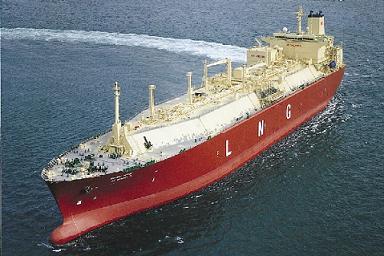
Fig:LNG carrier underway

Under normal operational conditions primary and secondary barrier spaces are continually swept with nitrogen. A small leakage of methane vapour through the membrane may not be readily obvious. However, indications are likely to be:
  1. A sudden rise in the percentage of methane vapour in one primary insulation space. Some porosity in the primary barrier weld will allow the presence of methane vapour in the primary insulation space. The amount of this vapour should be kept to a minimum by nitrogen purging.


  2. If a porosity fracture occurs in the primary membrane barrier below the level of the liquid in the tank, the vapour concentration will increase slowly and steadily.


  3. If the fracture is above the liquid level, the concentration will exhibit a fluctuating increase.


  4. An increase in pressure due to vapour leakage will be less obvious than an increase due to liquid leakage. This is because the volume of vapour passing through a fracture is small compared with the volume of liquid, which subsequently vaporises, passing through the same fracture. In both cases, volumes are likely to be small in comparison with the volume of the inter barrier space.


  5. A fracture above the liquid level in a cargo tank will allow direct flow of vapour into the primary insulation space. This flow will vary according to the pressure in the tank.


  6. A porosity fracture in the primary membrane below the liquid level in a cargo tank, resulting in a small amount of liquid vaporising as it passes through the fracture, will cause a small increase in pressure. This increase is dependent upon the height of liquid above the fracture and the pressure in the tank.


  7. No temperature change will be obvious, unless the fracture is in the immediate vicinity of the sensors below the cargo tank.


  8. Leakage of methane vapour into the primary insulation space presents no immediate danger to the tank or vessel. As much as possible information concerning the fracture and leak should be obtained and recorded. Ascertain whether the risk is increasing, as follows:


  9. After the leak is detected, and without changing the flow of nitrogen to the primary insulation space, record the gas concentration and primary space temperature every hour for eight hours.


  10. Then, if necessary, adjust the flow of nitrogen to maintain the gas concentration below 30% (vol) and record the gas concentration and primary insulation space temperature every four hours.


  11. In conjunction with the above, record all pressure changes occurring in the cargo tank and primary insulation space. Where there has been an LNG vapour leakage to a primary insulation space, the nitrogen supply controller should be set to the appropriate pressure setting and the space purged.

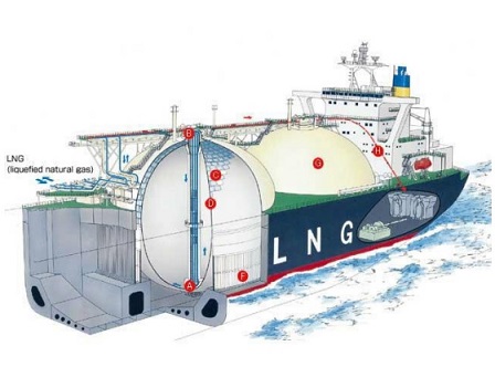
LNG tanks configuration


Leak from an LNG Tank – Ignited (for LNG Carriers)

An Ignited leak from LNG tank will result in fire or explosion. The most effective fire extinguishing agent for fires involving gas is dry powder. Following actions are recommended :

1) Raise the Fire Alarm (if it has not been detected by fire detecting system). Inform bridge, CCR.

2) Muster at fire stations. Check for missing or injured crew/personnel

3) Advise terminal and sound the pre-defined signal

4) Stop all cargo operations. Activate ESDS

5) Stop dual firing. FO only, isolate engine room from cargo side

6) Activate spray system

7) Consider - reduce speed, change course, head to deeper waters away from coast in order to avoid damage to third parties

8) Leave berth as soon as possible. Activate PERC system to release loading arms

9) Attend any injured people

10) Close the relevant isolation valves to prevent the spread of fire to the other cargo tanks and cargo pipes

11) Smoke divers should be ready and prepared as soon as possible

12) Chief Officer shall advise the Bridge (Master) regarding situation and possibilities of fire developing

13) Squad No.1 shall proceed to fire / explosion location in order to recover any missing crew/personnel

14) Squad No.2 shall cool down surroundings of fire location by means of fire hoses

15) Squad No.1 shall proceed to the location of the fire in order to tackle it. Technical Squad will be back-up team

16) Consider – whether any dangerous material is involved in the fire; consider the dangers of toxic fumes, flammable vapours, etc.

17) Shut down all fans and fire dampers/flaps, and water tight doors

18) Use water fire hoses for radiation protection in the approach to shut-off valves or to leaking jet

19) If fire cargo is involved in the fire do not apply water directly to the fire since it will provide a heat source for more rapid vaporisation of the liquid and therefore increase the fire

20) Consider - is external assistance needed

21) Consider - if we have to evacuate the area and activate fixed CO2 fire extinguishing system

22) If CO2 decided to be used. Raise CO2 alarm

23) Make sure nobody is in the location where CO2 will be released and all dampers, flaps and doors are closed and fans stopped

24) Chief Engineer will release the fixed CO2 system with authorisation of the Master

25) Consider - abandon vessel

26) Inform Owners, Insurance/ P&I

27) Consider – whether there is any possibility of oil spill or leakage. Try to minimise, confine.

28) Consider - running inert gas into void spaces


LNG liquid leakage to primary barrier (MEMBRANE)

A major failure in the primary membrane, allowing liquid into the primary insulation space, will be indicated as follows:
If a major failure of the membrane occurs, liquid from the tank will flow into the primary insulation space until the levels in both compartments are equal. When the contents of the cargo tank are discharged, unless the LNG in the primary insulation space can drain sufficiently quickly to the cargo tank, a differential liquid head will build up, tending to collapse the membrane of the tank.

Before discharging a tank with major failure in the primary membrane, it is essential that the primary membrane is punched so that liquid can freely flow back into the tank from the primary insulation space. In this way, no hydrostatic head occurs in the primary insulation space which could cause damage to the primary membrane support.

NOTE – UNDER NO CIRCUMSTANCES IS THE VESSEL TO OPERATE THE PUNCHING DEVICE WITHOUT PRIOR AUTHORISATION. AS THE USE OF THE PUNCHING DEVICE WILL RESULT IN EXTENSIVE REPAIRS, THE DECISION TO USE THE PUNCHING DEVICE WILL BE GIVEN AFTER CONSULTATION BETWEEN THE VESSEL, V.SHIPS AND THE VESSEL OWNERS.

The punching device is ship specific but often consists of a 30kg messenger which is dropped down the float gauge tube so as to punch a hole in the primary membrane at the base. The base of the float gauge tube is fitted with a split perforated base to allow the messenger to penetrate through to the membrane. The membrane is fitted with a thin diaphragm and the plywood insulation boxes are thinner than normal to allow the messenger to penetrate fully as per Barrier Punching Procedure. The tank can then be discharged safely.

The operating procedure for draining the inter barrier space is as follows:
  1. Operate the barrier punch system. It should be noted that during the discharge and until repairs have been completed, the primary insulation space of the damaged tank is to remain isolated from all other spaces and allowed to vent freely to atmosphere.
  2. Isolate the primary insulation space nitrogen supply to affected tank and allow venting to atmosphere via the vent mast.
  3. Discharge to another tank using the spray pump and spray main. A cargo pump could be used to discharge affected tank, but at a very slow rate.
  4. Start the affected tank spray pump in sequence, once the pump is running, slowly open the spray pump discharge valve into the spray main.

Water leakage to barrier (MEMBRANE) Ballast water leakage from the wing tanks to the insulation spaces can occur through fractures in the inner hull plating. If the leakage remains undetected and water accumulates in these spaces, ice accumulation can occur and cause deformation and possible rupture of the insulation. The resultant cold conduction paths forming in the insulation will cause cold spots to form on the inner hull.

The pressure differential caused by the head of water building up in the insulation space may be sufficient to deform or even collapse the membrane into the cargo tank. To reduce the risk of damage from leakage, each cargo insulation space is provided with water detection units. A bilge piping system is used for the removal of any water.

Bilge wells are provided in each of the transverse cofferdam spaces and are fitted with independent level alarms. The tank secondary insulation space is connected to the bilge wells by means of a drain pipe. The bilge wells are connected to a draining pipe system with a dedicated bilge pump, of sufficient capacity, situated in each of the cofferdams for discharging the water to deck level and then overboard. If ballast water is suspected of having leaked into a secondary insulation space, appropriate arrangements must be made, such as the following:

1. Pump out the ballast water from adjacent wing tanks with consideration to vessel’s stability and stress condition.

2. Ventilate the required cofferdam and carry out normal enclosed space entry.

3. Connect a flexible hose to the pump outlet valve in order to drain the water discharge overboard via a scupper pipe.

4. Open the pump outlet valve on the deck.

5. Start the pump and continue pumping until the maximum amount of water has been discharged.

6. Carry out an inner hull inspection to determine the cause of the leak, with particular reference to a safe atmosphere in the ballast tank space.

7. After the maximum possible amount of water has been discharged from the insulation space, appreciable moisture will remain in the insulation and over the bottom area. Increasing the flow of nitrogen through the space can assist in drying out of the insulation.


LNG liquid leakage to drip pan (MOSS)

A serious failure of the tank structure, allowing liquid into the insulation space or hold space, will be indicated as follows:
  1. A rapid increase in the methane content of the affected space.
  2. Low temperature alarms at the temperature sensors in the surrounding areas.
  3. A general lowering of inner hull steel temperatures.
  4. Possible liquid alarms in the surrounding areas.
  5. Possible gas alarms in the surrounding areas.

In case of leakage from the northern hemisphere, it will drain by gravity and collect in the drain channel at the wedge space, namely, the skirt to tank joint. From this drain channel, it passes the wedge space via numerous drain holes cut in the skirt and gravitates to the southern hemisphere. The leakage will eventually collect in the drain tube which contains the rupture disc and, from there, after the rupture of the disc, to the drip pan.

Any leakage from the southern hemisphere will drain directly by gravity between the tank and the insulation to the drain tube.

If leakage of cargo into the hold space occurs, the oxygen content of the space must be reduced to below the explosive limit by the use of inert gas or nitrogen. Inert gas is introduced via the hold space aeration header to the hold space bottom and is exhausted to the atmosphere from the top of the hold space.


Water leakage to cargo hold space (MOSS)

Ballast water leakage from the wing tanks to the hold spaces can occur through fractures in the inner hull plating. If the leakage remains undetected and water accumulates in these spaces, ice may be formed. Ice accumulation can cause deformation and possible rupture of the tank insulation. The resultant cold conduction paths forming in the insulation may cause cold spots to form.

To reduce the risk of damage from leakage, detector units are located in each cargo tank hold space.

The leakage protection system also includes a method of collecting and accumulating small leaks of liquid cargo as well as water. The water is collected in a well at the after end of the hold space under the cargo tank. The water leakage collects in this sump where monitoring equipment in the form of liquid and temperature indicators is installed. In addition, gas detectors are situated in various locations within the hold space.

Any liquid collecting in the sump will raise a liquid alarm and, by observing temperature and gas indicators, it is possible to determine whether the liquid is cargo due to tank leakage or water due to leakage from the ballast tanks.

A bilge ejector is installed in the sump to empty any water leakage from the hold space.


Leakgae of liquefied gas into hold spaces

The Master must judge whether liquefied gas has leaked into a hold space, paying attention to a measured value by a gas detecting device, changes in hold pressure and temperature, and take the following response actions in consultation with the Company.

The hold space where a gas leak is detected, must be isolated from other holds and inerted immediately. The inert gas generator (IGG) must be continuously operated so as to lower the Oxygen concentration below 8%.


Handling with cargo eductor

When it is considered transfer of the leaked liquefied gas is necessary, the leaked liquefied gas must be transferred to other cargo tanks by a cargo eductor in the following procedure.
Shifting to another cargo tank

The liquefied gas contained in a cargo tank from which liquefied gas has leaked, must be shifted to another cargo tank with sufficient ullage by use of a cargo pump.


The majority of liquefied gases are clean, non-polluting, products and create no danger to the marine environment. If however certain liquefied gases spill on to the sea you should be aware that they may:

The Data Sheets will give information on pollution, if any Pollution is most likely to occur during cargo or bunkering operations:
  • if the operation is not correctly monitored
  • if the cargo hose or loading arm connections are not properly made
  • when disconnecting cargo lines that have not been drained.
  • if moorings are not checked and excessive strain is placed on the cargo connections or the ship "breaks out" of the berth.
  • if cargo equipment is not properly maintained


  • Related Information:

    1. Leaks from a Loading Arm due to Tidal or Current Effects


    2. Low temperature effects of Liquefied gases


    3. Minor or major leaks from LNG tanks


    4. Connection and disconnection of cargo hoses and hard arms


    Risk of Overfilling of Cargo Tank during Loading

    Cargo tank ruptures due to increased pressure - emergency procedure for gas carriers

    Gas carrier Emergency Procedures for rescue

    Defining various gas carrier types

    Fuel flexibility of LNG ships

    LNG ship spillage risk

    LNG shipment

    Initial Cool Down of cargo tanks

    Leaks on the Cargo System, Continuous Flow - how to prevent

    LNG tank leaks and immediate action by gas carriers

    Leaks from a Loading Arm due to Tidal or Current Effects

    Minor or major leaks from LNG tanks

    Procedures for LNG cargo loading

    Procedures for LNG cargo discharging


    External links :


    1. International maritime organization


    // Home page/// LNG handling /// LPG handling/// Sea transport /// Gas products///

    Cargo work ///Fire precautions ///Health hazards ///Safety Precautions

    ///Emergency response ///


    Copyright © Liquefied Gas Carrie.com All rights reserved.


    The content published in this website are for general reference only. We have endeavoured to make the information as accurate as possible but cannot take responsibility for any errors. For latest information please visit www.imo.org . Any suggestions, please Contact us !

    ///Links &Resources // Terms of use/// Privacy policy///Home page///