

Home page|||
LNG handling |||
LPG handling||| Other Gas products|||
Fire & Safety|||
Emergency response |||
Onboard procedures for discharging LNG cargo - gas carrier safety guide
Liquefied natural gas (LNG) Natural gas comes from natural sources and is composed of
methane, ethane, propane and small amount of butane. It is condensed to about 1/600 of
the volume by cooling it to below the -160°C, its boiling point, to produce LNG.
Liquid LNG is pumped ashore by use of two submerged pumps installed at the bottom of each tank. In the process, the cargo tank pressure shows a decreasing tendency as the LNG level drops in the tank, resulting from the discharge of LNG. Conversely, shore tank pressure shows an increasing tendency with the receipt of LNG.
By use of the pressure difference between shore and vessel cargo tanks, LNG gas in the shore tank is sent to the vessel cargo tank. However, when LNG is discharged at a higher rate, the vessel cargo tank shows a declining tendency and, therefore, LNG gas is forced into the vessel cargo tank with a shore blower, to maintain the vessel tank pressure. As another way, part of the LNG to be discharged is vaporized with a vaporizer of the vessel and the BOG is delivered to cargo tanks.
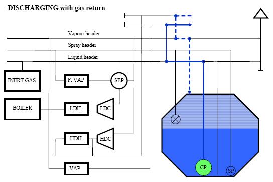
Fig:LNG discharging with gas return
Procedure for LNG discharging with vapour return
Confirm liquid manual/automatic manifold valves are open.
Manually close the liquid manifold cool down valves.
Prior to cargo pump start, confirm that all liquid branch valves are closed and all filling valves are
opened. Also notify the engine room to verify that sufficient generator capacity is available.
Start the cargo pumps as per established guidelines. It is important that the shore is made aware
of when pumps will be coming on line and the consequent changes in their tank pressures then
can expect.
The usual procedure is to start two pumps on re-circulation on one tank, then commence discharge
from the tank. This usually takes 5 minutes. A similar procedure is then applied to the other tanks
with a 5 min period between each tank. Once all pumps are running on 60 % load then slowly
increased in turn to maximum specified load.
As tank pressure falls, request receiving terminal to start to send vapour back to the ship and
maintain tank pressure at agreed level. Monitor the following items during discharge.
- Cargo tank level
- Cargo tank pressure
- Cargo pump motor load and discharge pressure
- Draft, trim and heel
- Ship condition
If stripping is planned for several tanks, it is recommended to keep the tank levels slightly different
in each tank in accordance to the established ramp down procedures.
Request the receiving terminal to stop the return gas blower to keep adequate tank pressure. After
discharging, at least one filling valve is kept open to avoid pressurization of the liquid line.
Liquid draining and vapour purging of the arms is performed after completion of cargo discharging.
After completing of draining and purging, the following operations are carried out.
- Final gauging after discharging
- Arm disconnection and de-icing (if necessary)
- Water curtain is stopped.
NB refer to ship specific cargo manual regarding maximum and minimum allowable
liquid levels for sea passage.
Discharging without vapour return
In rare instances such as gassing up a new terminal it may be necessary to discharge without the
use of a shore return. In this instance the LNG is bled from the main liquid line to the vaporizer.
The rate of vaporization is adjusted to maintain a constant tank pressure.
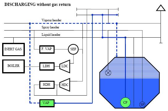
Fig:LNG discharging without gas return
Cargo heel
Subject to the trading patterns of the vessel and any particular requirements of the charterer, a
cargo heel may be required. The heel quantity is allowed for in the discharge plan and the pumps
are to be stopped at the required ullages. Each ship will have its own specific instructions within
the Operating manual, detailing the required quantities and the procedures to be followed in taking
tanks down to this level. The heel figures should be carefully calculated, to ensure that there is
maximum outturn of cargo at the discharge port, consistent with being able to arrive at the
loadport with tanks cooled down by the onboard retained heel.
(Note: When the liquid level reaches 1 metre or less, avoid stopping the pump if at all possible
until the cargo has been fully discharged. If the shore facility is unable to accept the liquid for
intermittent periods it is better to keep the pump going and recirculate back into the tanks until
discharge can be resumed and completed.)
All LNG remaining in the downward leg of the loading arms and manifold connection is to be
drained to the tanks through the liquid line assisted by nitrogen pressure from ashore. The LNG
and vapour manifolds are then purged with nitrogen until an acceptable hydrocarbon content is
reached.
The retention of heel is subject to much discussion, and will vary with the type of vessel. On
membrane vessels on shorter ballast voyages it is acceptable to carry a small amount of heel in
each of the cargo tanks, and generally this will maintain the tank bottom temperature sufficiently
cold that the vessel is able to berth and commence loading without additional tank cooldown being
necessary. Care should be taken that the spray pump can be started at any time during the voyage
if required.
On longer voyages it is usual for the heel to be retained in one tank, with others heeled out.
Additional spraying may be necessary when cargo tank temperature is higher than the ATR (arrival
temperature requirement) which is generally accepted as being < -130 degC. Terminal
requirements should also followed as appropriate. The intention being for the vessel to arrive
without the requirement for extended cooldown and delays at the load port.
NOTE, on long ballast voyages with large quantities of heel retained in one tank, it is essential that
the quantity of heel carried does not exceed the quantity corresponding to a 10% of the tank
height .
On Moss vessels, it is usual for the heel to be retained in one tank, with others heeled out. After
departure the LNG in the heeled out tanks will be further reduced by transferring cargo to the
dedicated holding tank. The tanks are then sprayed on passage to cooldown to a level where
loading take place without delay at the loadport.
Occasionally on shorter voyages, Moss vessels will retain the heel distributed across all tanks.
At the last discharge before the vessel is scheduled to warm up, say for drydock, all tanks are
generally heeled out as far as possible, to avoid leaving excessive quantities of LNG which needs to
be warmed up and vented to atmosphere on passage to the docking port
Draining / purging
The procedures for draining / purging of the manifold lines and ships liquid lines are the same
whether the ship has been loading or discharging. This is done by using a Nitrogen punch
method. After completion of loading or discharging, this operation is carried out prior to
disconnecting the liquid and vapour arms.
On completion the manifold ESD valves are closed and the spray line is lined up from the manifold
to all tanks via the spray return valves. The cool down valve on each manifold is kept closed. Then
the terminal raises the pressure within the arms to a certain level (normally around 4 kgs/cm2).
Then the spray cool down valve are opened up and LNG liquid and vapour in the liquid arm is fed
to the cargo tanks through the spray line by Nitrogen (N2) pressure.
Vapour in the vapour arm is fed to the cargo tanks through the vapour header by N2 gas supplied
from the terminal.
Draining is normally carried out by pressuring the arms one by one.
The procedure is repeated until the arm is completely free of liquid and the hydrocarbon level is
below 1% by volume. Remember that the allowed hydrocarbon concentration might vary from
terminal to terminal.
Draining of the ships liquid lines is done by opening up the spray bypass valve at the manifold. As
the pressure increases in the liquid line the liquid will be led through the spray line and back to the
cargo tank.
Vapour from shore valve
After any discharge operation, when the shore vapour arm has been disconnected and the vapour
manifold closed, the vapour from shore valve is to be re-opened and then left open at least 20%.
This will allow any increase in pressure, during the subsequent line warm up, to be transferred via
the vapour header to the individual cargo tanks. Any excessive increase in pressure within the
cargo tanks will initially be regulated by the automatic vent valve to the forward vent riser. If the
pressure is not controlled sufficiently by the automatic vent valve, then individual tank relief valves
will operate to vent pressure via the individual mast risers.
Below is our additional guideline for handling LNG cargo:
Liquefied gases - How to remove all cargo liquid from tanks
Preparation for discharging LNG cargo
Preparation for loading LNG cargo
Inerting of Cargo Tanks prior loading LNG cargo
Gassing-up requirement for cargo tanks
Initial Cool Down of cargo tanks
LNG spill risk during marine transportation and hazards associated
Toxicity and associated health hazards in liquefied Gas Carrier
Safety check items prior loading LNG cargo
Details of various cargo handling equipment onboard
Related Information:
-
Liquefied gas carrier safety training
- Increased Cargo Capacity for LNG ships & Advantages of the dual fuel diesel electric propulsion
Defining various gas carrier types
Fuel flexibility of LNG ships
LNG shipment
Initial Cool Down of cargo tanks
Leaks on the Cargo System, Continuous Flow - how to prevent
LNG tank leaks and immediate action by gas carriers
Leaks from a Loading Arm due to Tidal or Current Effects
Minor or major leaks from LNG tanks
Procedures for LNG cargo discharging
External links :
-
LNG jornal, news, forums and latest industry news
// Home page///
LNG handling ///
LPG handling///
Sea transport ///
Gas products///
Cargo work
///Fire precautions
///Health hazards
///Safety Precautions
///Emergency response ///
Copyright © Liquefied Gas Carrie.com All rights reserved.
The content published in this website are for general reference only. We have endeavoured to make the information
as accurate as possible but cannot take responsibility for any errors. For latest information please visit www.imo.org .
Any suggestions, please Contact us !
///Links &Resources //
Terms of use///
Privacy policy///Home page///