Prior to commencing the loading operation the cargo pipelines have to be cooled. The primary reasons for cooling the cargo lines are:
i) To minimize the possibility of leaks being created at joints with valves or other sections of pipeline as they contract when cargo is passed.
ii) To reduce the possibility of sudden shock loadings on bellows as pipes contract rapidly.
iii) To avoid the formation of vapor locks in the pipelines when cargo is introduced. If LNG is introduced into a warm pipeline the initial cargo will vaporize, create a large pressure that can block the loading of the liquid. It is then possible that this vapour will then condense very rapidly as the temperature reduces below the condensation point, allowing the liquid to surge along the pipeline possibly resulting in damage to the pipelines, valves or connections.
Air purge of loading arms
After the connection of loading arms, air should be purged from the loading arms and the tips of manifold pipes. N2 gas is lead into the loading arms from injection lines connected to the arms, and then pressurize up to about 4 to 6 kg/cm2G.
After pressurization, the ships liquid manifold vent valve and vapor manifold vent/drain valve are opened to release air and N2 gas into the atmosphere. While this operation is repeated two or three times, a leak test (with soap solution) is conducted at the same time. Air purge comes to an end when the oxygen content of the purged gas has dropped below 2%.
Loading Arms Cool Down
The cool down of the loading arms is performed from shore side by use of a small capacity pump. At a discharge port, the arms are cooled down by sending in LNG by ships spray pump.
Loading Operation
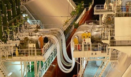
LNG is loaded via the loading manifolds to the liquid header and then to each tank filling line.
The boil-off and displaced vapour leave each tank via the vapour suction to the vapour header. The vapour is initially free-flowed to shore via vapour crossover manifold and, as tank pressure rises, one compressor is brought into operation to increase the gas flow to shore and limit the vapour main and cargo tank pressure.
As the loading rate increases, it is important to monitor the tank pressures and to start one HD compressor. If the compressors are unable to cope with the volume of boil-off and displaced gas, it will be necessary to reduce the loading rate.

Fig:LNG bulk loading diagram
Bulk loading
When all lines and valves are fully cooled the vessel can commence ramping up the loading rate in
the sequence agreed with the terminal. Deballasting should be commenced in accordance with the
cargo plan. The cargo should be evenly distributed during the loading.
Ensure the HD compressors are adjusted in line with loading rate to ensure that the tank vapour
pressure remains at a level safely below the lifting pressure of the relief valves. Ensure Nitrogen
system is performing correctly.
Moss vessels will require the temperature gradient (with particular reference to the equator) to
remain within certain limits, the tank temperatures are therefore to be closely monitored. Hourly
temperatures are to be recorded in order that if required the vessel can verify that temperature
has stayed within the manufacturers tolerances.
If not already started membrane ships should start appropriate cofferdam heating.
Communications with the terminal should be tested on a frequent basis. Remote gauging devices
and valve position indicators should be verified against local readouts at regular intervals during
the operation. Moorings should be diligently attended and vessel movement with respect to loading
arms closely monitored, if required additional persons are to be called to assist with the moorings.
If at any time the OOW is in doubt a senior officer or the Master should be called.
Topping off
As the vessel approaches completion of cargo operations the tanks should be staggered in line with
the cargo plan, typically this would leave a gap of 10 to 15 minutes between completion of each
tank. The terminal is to be notified well in advance and in line with the agreed procedure that the
vessel is topping of and will need to reduce loading rate. Notification should be made at least 30
minutes before reducing rate.
Note: Membrane tanks normally fill to 98% where as Moss vessels normally fill to 99.5%.
On all vessels the independent alarms activate at preset filling levels, the upper alarm activates the
ESD if previous alarms are ignored.
Deballasting
The deballasting operation is carried out simultaneously with the cargo loading operation.
Before any de-ballasting commences, all ballast surfaces should be visually checked and confirmed
as free from oil or other pollutants. This check must be carried out through inspection hatches /
tank lids. This is particularly important for ballast tanks which are situated adjacent to fuel oil
tanks. If fitted, gas detection / sampling systems may not indicate the presence of hydrocarbons
particularly in small quantities.
Deballasting is initially carried out by gravity discharge until the level in the ballast tanks approach
the vessels water line when the ballast pumps are used.
The ballast should be adjusted to keep a small stern trim to aid with the stripping of the ballast
tanks.
The flow rate of the ballast should be adjusted to keep the ship within 1 meter of the arrival draft
or as specified by the terminal.
Deballasting should normally be completed before the start of the topping off of the cargo tanks.
Filling Rate of Cargo Tanks
The IGC Code (International Code for the Construction and Equipment of Ships Carrying Liquefied Gases in Bulk) came into force on July 1, 1986, in accordance with the International Convention on the Safety of Life at Sea, 1983 (the 1974 SOLAS Convention, as amended in 1983), and, following this, the Regulations Relating to the Carriage and Storage of Dangerous Goods by Ship was revised in Japan. The IGC Code contains a chapter for Filling Limits for Cargo Tanks.
LNG carriers registered in Japan are NK-class ships and constructed on the basis of NKs Rules and Guidance for the Survey and Construction of Steel Ships Part N. These rules reflect the IGC Code, as it is, and, as a result, our LNG carriers, though built before the enforcement of the 83 SOLAS Convention, meet requirements for new ships in the IGC Code.
Behaviour of LNG in the cargo tanks
When loaded in the cargo tanks, the pressure of the vapour phase is maintained substantially
constant, slightly above atmospheric pressure.
The external heat passing through the tank insulation generates convection currents within the
bulk cargo, causing heated LNG to rise to the surface where it vaporizes.
The heat necessary for vaporization comes from the LNG, and as long as the vapour is
continuously removed by maintaining the pressure as substantially constant, the LNG remains at its
boiling temperature.
If the vapour pressure is reduced by removing more vapour that is generated, the LNG
temperature will decrease. In order to make up the equilibrium pressure corresponding to its
temperature, the vaporization of LNG is accelerated, resulting in an increase heat transfer from
LNG to vapour.
If the vapour pressure is increased by removing less vapour than is generated, the LNG
temperature will increase. In order to reduce the pressure to a level corresponding to the
equilibrium with its temperature, the vaporization of LNG is slowed down and the heat transfer
from LNG to vapour is reduced.
LNG is a mixture of several components with different physical properties, particularly the
vaporization rates; the more volatile fraction of the cargo vaporizes at a greater rate that the less
volatile fraction. The vapour generated by the boiling of the cargo contains a higher concentration
of the more volatile fraction than the LNG.
The properties of the LNG, i.e. the boiling point, density and heating value, have a tendency to
increase during the voyage.