Liquefied Gas Carrier

Home page||| LNG handling ||| LPG handling||| Other Gas products||| Fire & Safety||| Emergency response |||

Cargo Containment Systems in Liquefied Gas Carriers

Cargo tank of gas carrier – The liquid-tight shell designed to be the prime container of the cargo and includes all such containers whether or not associated with insulation or secondary barriers or both, (IGC Code). The IGC Code categorizes cargo tanks into five main types; integral tanks, membrane tanks, semi-membrane tanks, independent tanks, and internal insulation tanks. In addition, independent tanks include a further three subcategories of tanks referred to as Type A, Type B and Type C, while internal insulation tanks include two sub-categories of Type 1 and Type 2 tanks.

For transferring LNG as a cargo IMO type B (Moss Maritime spherical tanks) and membrane tanks (Gaz Transport and Technigaz) mainly are used. New developments use IMO type A tanks and IMO type C tanks. For LNG propulsion on ship other than LNG carriers, IMO type C tank are preferable.
LNG carrier cargo tank cross section


A cargo containment system is the total arrangement for containing cargo including, where fitted:
  1. A primary barrier (the cargo tank),
  2. Secondary barrier (if fitted),
  3. Associated thermal insulation,
  4. Any intervening spaces, and
  5. Adjacent structure, if necessary, for the support of these elements


For cargoes carried at temperatures between –10 degree C and -55 degree C, the ship’s hull may act as the secondary barrier and in such cases it may be a boundary of the hold space.

The basic cargo tank types utilized on board gas carriers are in accordance with the list below:-

Independent Type ‘A’: Some other types such as:

Independent Type ‘B’: Internal insulation Type ‘1’

Independent Type ‘C’: Internal insulation Type ‘2’

Membrane: Integral
Various LNG carrier
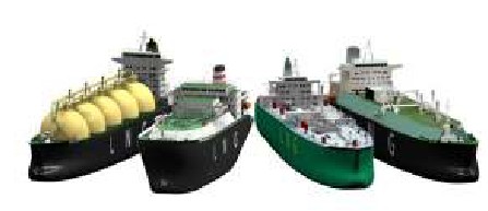
Fig:Various type LNG carrier

Independent Tanks

Independent tanks are completely self-supporting and do not form part of the ship’s hull structure. Moreover, they do not contribute to the hull strength of a ship. As defined in the IGC Code, and depending mainly on the design pressure, there are three different types of independent tanks for gas carriers: these are known as Type ‘A’, “B’ and ‘C’.
LNG carrier membrane gaz transport
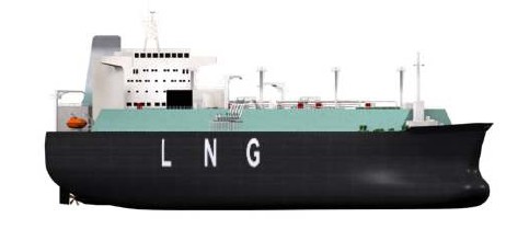
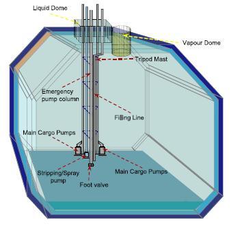
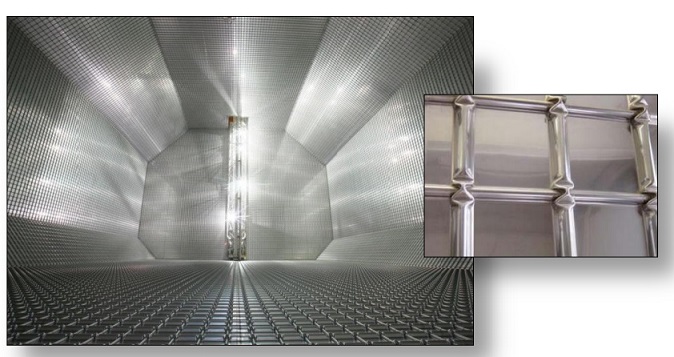
Fig:LNG carrier membrane gaz transport

Type ‘A’ Tanks

Type ‘A’ tanks are constructed primarily of flat surfaces. The maximum allowable tank design pressure in the vapour space of for this type of system is 0.7 barg; this means cargoes must be carried in a fully refrigerated condition at or near atmospheric pressure (normally below 0.25 barg).

This type of tank as found on a fully refrigerated LPG carrier. This is a self-supporting prismatic tank which requires conventional internal stiffening. In this example the tanks is surrounded by a skin of foam insulation. Where perlite insulation is used, it would be found filling the whole of the hold space.

The material used for Type ‘A’ tanks is not crack propagation resistant. Therefore, in order to ensure safety, in the unlikely event of cargo tank leakage, a secondary containment system is required. This secondary containment system is known as a secondary barrier and is a feature of all ships with Type ‘A’ tanks capable of carrying cargoes below -10 degree C.

Fully refrigerated LPG tanker structure
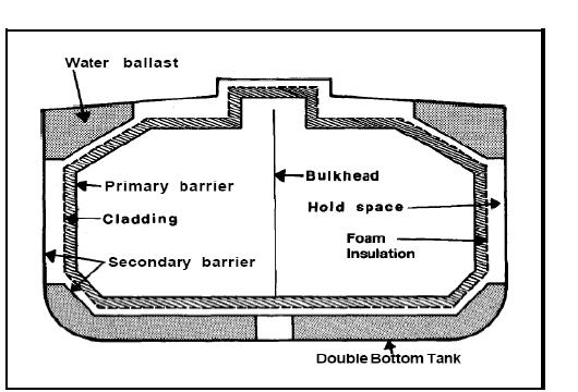
Type A tank - Fully refrigerated LPG tanker structure

For a fully refrigerated LPG carrier (which will not carry cargoes below –55 degree C) the secondary barrier must be a complete barrier capable of containing the whole tank volume at a defined angle of heel and may form part of the ship’s full, as shown in the figure.

In general, it is this design approach which is adopted. By this means appropriate parts of the ship’s hull are constructed of special steel capable of withstanding low temperatures. The alternative is to build a separate secondary barrier around each cargo tank.

The IGC Code stipulates that a secondary barrier must be able to contain tank leakage for a period of 15 days.

On such ships, the space between the cargo tank (sometimes referred to as the primary barrier) and the secondary barrier is known as the hold space. When flammable cargoes are being carried, these spaces must be filled with inert gas to prevent a flammable atmosphere being created in the event of primary barrier leakage.
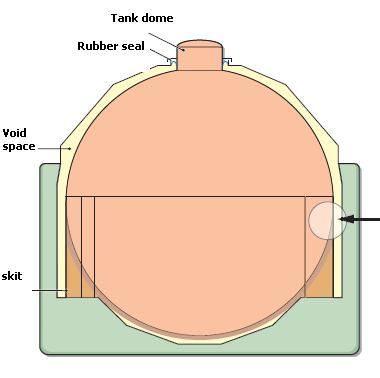
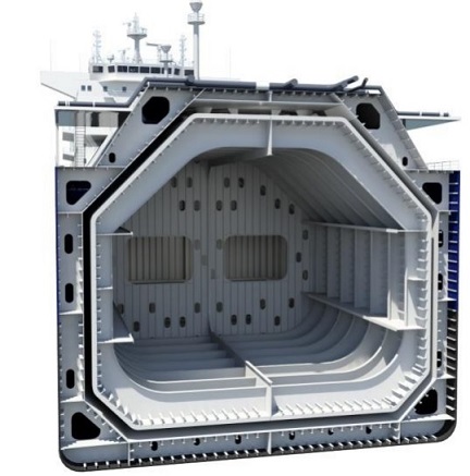
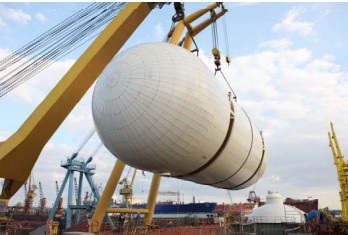
IMO type B tank
IMO type B tank

Moss Rosenberg insulation technology
IMO type B tank- Moss Rosenberg insulation technology


Type ‘B’ Tanks

Type ‘B’ tanks can be constructed of flat surfaces or they may be of the spherical type. This type of containment system is the subject of much more detailed stress analysis compared to Type ‘A’ systems. These controls must include an investigation of fatigue life and a crack propagation analysis. The most common arrangement of Type ‘B’ tank is a spherical tank. This tank is of the Kvaerner Moss design.

Because of the enhanced design factors, a Type ‘B’ tank requires only a partial secondary barrier in the form of a drip tray. The Type ‘B’ spherical tank is almost exclusively applied to LNG ships; seldom featuring in the LPG trade. A type ‘B’ tank, however, need not be spherical.

There are Type ‘B’ tanks of prismatic shape in LNG service. The prismatic Type ‘B’ tank has the benefit of maximizing ship-deck. Where the prismatic shape is used, the maximum design vapour space pressure is, as for Type ‘A’ tanks, limited to 0.7 barg.
LNG carrier moss tanks
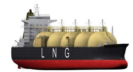
Fig:LNG carrier moss tanks


Most Moss type vessels have 4 or 5 tanks. The insulation in these tanks is provided by thick layer of foam insulation around the tank. The tanks are checked for any leakages by nitrogen atmosphere in special thin layer called “tinfoil”. This layer also allow the insulation to remain dry.

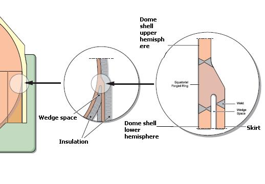
These tanks are susceptible to contraction and expansion during cool down and warm up, so that can reach even 2 foots(0,6098m) . For these reason all piping come into the tanks through the top part and are connected to the ships lines via flexible bellows. The skit is also constructed to endure changes in tank diameters, as well as it has enough to transfer successfully tanks weight to ships hull. The pressure in this tanks usually don't exceed 55kPa (0.55bar) but in emergency cases it can reach the 1 bar pressure.

Type ‘C’ Tanks

Type ‘C’ tanks are normally spherical or cylindrical pressure vessels having design pressures higher than 2 barg. The cylindrical vessels may be vertically or horizontally mounted. This type of containment system is always used for semi-pressurized and fully pressurized gas carriers.

In the case of the semi-pressurized ships it can also be used for fully refrigerated carriage, provided appropriate low temperature steels are used in tank construction. Type ‘C’ tanks are designed and built to conventional pressure vessel codes and, as a result, can be subjected to accurate stress analysis. Furthermore, design stresses are kept low. Accordingly, no secondary barrier is required for Type ‘C’ tanks and the hold space can be filled with either inert gas or dry air.

IMO type C tank
IMO type C tank

In the case of a typical fully pressurized ship (where the cargo is carried at ambient temperature), the tanks may be designed for a maximum working pressure of about 18 barg. For a semi-pressurized ship the cargo tanks and associated equipment are designed for a working pressure of approximately 5 to 7 barg and a vacuum of 0.5 barg. Typically, the tank steels for the semi-pressurized ships are capable of withstanding carriage temperatures of -48 degree C for LPG or -104 degree C for ethylene. (Of course, an ethylene carrier may also be used to transport LPG.)

Type ‘C’ tanks as fitted in a typical fully pressurized gas carrier. With such an arrangement there is comparatively poor utilization of the hull volume; however, this can be improved by using intersecting pressure vessels or bi-lobe type tanks which may be designed with a taper at the forward end of the ship. This is a common arrangement in semi-pressurized ships.


Membrane Tanks (membrane – 0.7 to 1.5 mm thick)

The concept of the membrane containment system is based on a very thin primary barrier (membrane – 0.7 to 1.5 mm thick) which is supported through the insulation. Such tanks are not self-supporting like the independent tanks. An inner hull forms the load bearing structure. Membrane containment systems must always be provided with a secondary barrier to ensure the integrity of the total system in the event of primary barrier leakage.

LNG carrier membrane tank design
LNG membrane design

The membrane is designed in such a way that thermal expansion or contraction is compensated without over-stressing the membrane itself. There are two principal types of membrane system in common use – both named after the companies who developed them and both designed primarily for the carriage of LNG. These two companies have now combined into one.


Semi-Membrane Tanks

The semi-membrane concept is a variation of membrane tank system. The primary barrier is much thicker than in the membrane system, having flat sides and large roundish corners. The tank is self-supporting when empty but not in the loaded condition. In this condition the liquid (hydrostatic) and vapour pressures acting on the primary barrier are transmitted through the insulation to the inner hull as is the case with the membrane system. The corners and edges are designed to accommodate expansion and contraction.

Although semi-membrane tanks were originally developed for the carriage of LNG, no commercial-size LNG carrier has yet been built to this design. The system has, however, been adopted for use in LPG ships and several Japanese-built fully refrigerated LPG carriers have been delivered to this design.


Integral Tanks

Integral tanks form a structural part of the ship’s hull and are influenced by the same loads which stress the hull structure. Integral tanks are not normally allowed for the carriage of liquefied gas if the cargo temperature is below -10 degree C. Certain tanks on a limited number of Japanese-built LPG carriers are of the integral type for the dedicated carriage of full refrigerated butane.

LNG tanks internal barrier


Internal Insulation Tanks

Internally insulated cargo tanks are similar to integral tanks. They utilize insulation materials to contain the cargo. The insulation is fixed inside ship’s inner hull or to an independent load-bearing surface. The non-self-supporting system obviates the need for an independent tank and permits the carriage of fully refrigerated cargoes at carriage temperatures as low as -55 degree C.

Internal insulation systems have been incorporated in a very limited number of fully refrigerated LPG carriers but, to date, the concept has not proved satisfactory in service.


Related Information:

  1. Tank construction materials for a modern gas tanker


  2. LNG vessel construction -Advantages of membrane technology


  3. Advantages of Moss rosenberg cargo containment system


  4. Type of gas carriers - variation in the design, construction and operation


  5. Transporting liquefied natural gases by LNG ships


  6. Cargo conditioning, reliquefaction and boil-off control requirement for a liquefied gas carrier


  7. The sea transport of liquefied gases in bulk -Where do the products come from ?

  8. Tank construction materials for a modern gas tanker


  9. LNG vessel construction -Advantages of membrane technology


  10. Advantages of Moss rosenberg cargo containment system


  11. Type of gas carriers - variation in the design, construction and operation


  12. Transporting liquefied natural gases by LNG ships


  13. Cargo conditioning, reliquefaction and boil-off control requirement for a liquefied gas carrier


  14. The sea transport of liquefied gases in bulk -Where do the products come from ?


// Home page/// LNG handling /// LPG handling/// Sea transport /// Gas products///

Cargo work ///Fire precautions ///Health hazards ///Safety Precautions

///Emergency response ///


Copyright © Liquefied Gas Carrie.com All rights reserved.


The content published in this website are for general reference only. We have endeavoured to make the information as accurate as possible but cannot take responsibility for any errors. For latest information please visit www.imo.org . Any suggestions, please Contact us !
//Links &Resources // Terms of use// Privacy policy //Home page